


Using STM32 Discovery Board (ST-Link v1) With VisualGDB

- Details
- Published: Thursday, 09 June 2016 12:36
- Written by Dub Bartolec
These days it happens to be that everything that has USB interface and it is connected to PC pretty much works out of the box.
Mainly it is like that, but from time to time it happens to be that certain combination of USB devices and certain software packages just don't work together when we need them most. When internet search for the solution to the similar problem doesn't give any result we often face hours of desperation trying to get something going burning valuable time. We've had similar situation recently.
In the past, I've used number of boards (MSP430, STM32, K6 and others) boards to make quick proof of concept solutions that can be demonstrated to clients during decision making phase of the projects to be deployed in IoT, M2M. They all worked fine until I've stumbled upon a batch of cards that just refused to be programmed from VisualGDB (IDE extension for Visual Studio).
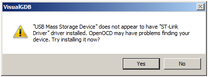
Those particular boards were STM32VLDISCOVERY. Initially their USB interfaces were recognized by the VisualGDB as ST-Link v1 but on an attempt to test the connection they just did not work and it appeared that driver was not compatible with ST-Link. Those boards could easily be programmed by the STM32 STLink Utility.
If you end up in the same situation and it happens to be that you have another STM32 development board that you know it works and it has selectable SWD pins than you can use it to reprogram and debug stubborn board from VisualGDB.
In our case we've had one STM32nucleo board and we used to acomplish exactly that. For the start identify that both boards have SDM (One on the left is STM Discovery board with ST-Link/V1 and board on the right is STM32Nucleo with STLink/V2.
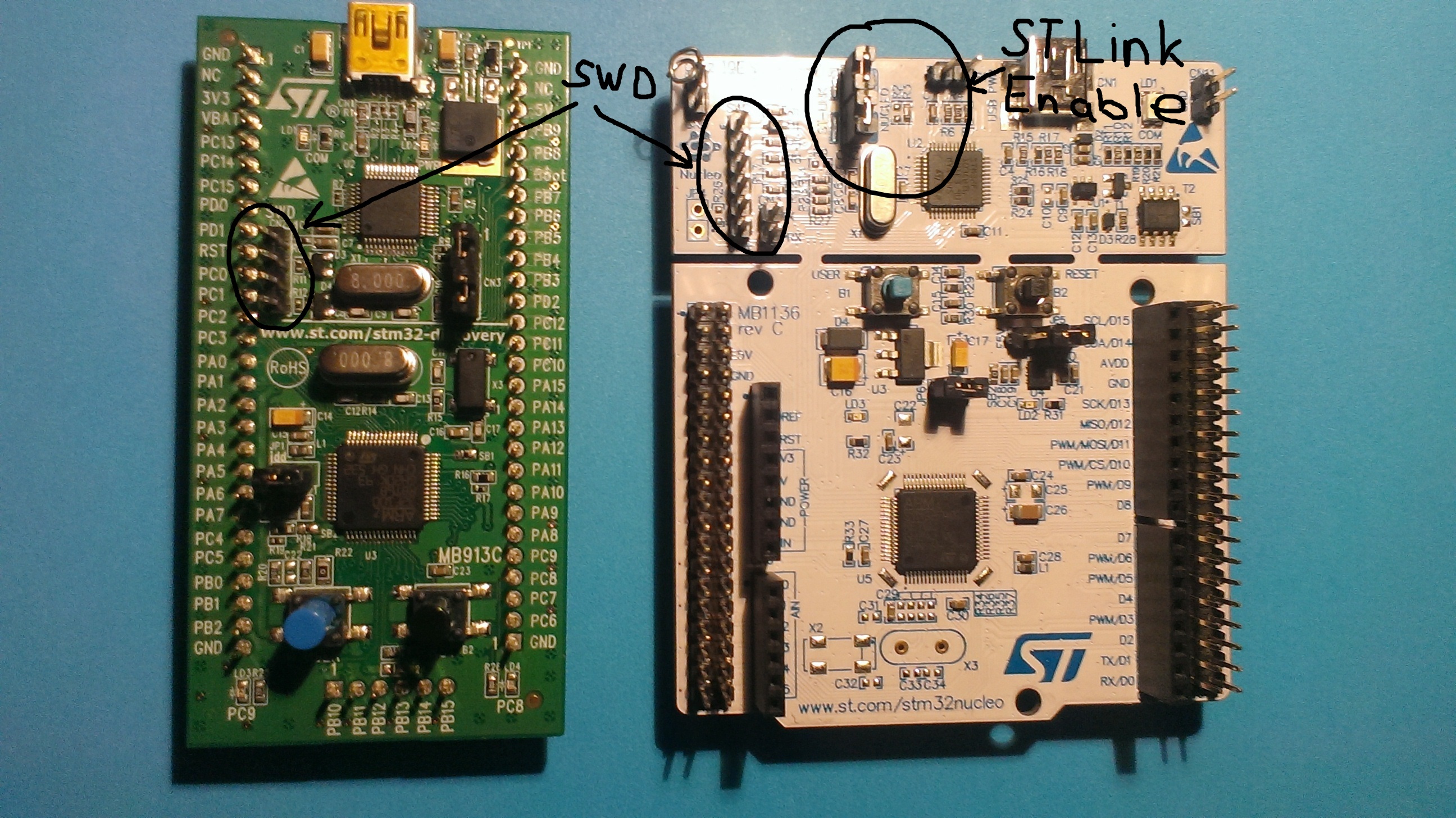
- In order to get it all going remove ST-Link jumpers on donor board so its CPU is isolated from JTAG.
- Connect SWD connectors on both boards to each other in a straight connection using only 4 pins (Pin1 to Pin2, Pin2 to Pin3, etc). If both boards support 6 Pin SWD connect them all.
- Make sure that board that is to be programmed is powered by 3.3V. In this case we brough the power from Nucleo board as seen on image bellow:
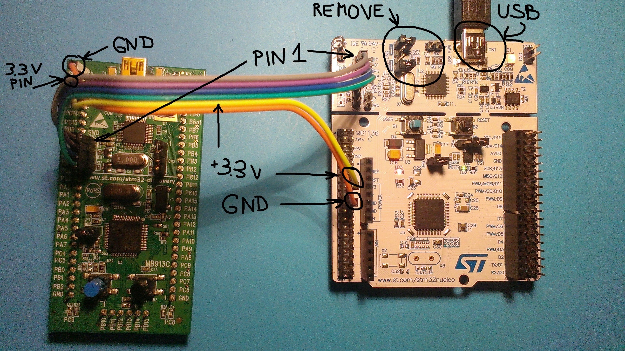
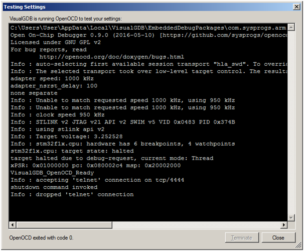
All that is left now is to connect USB to donor board, start VisualGDB and program stubborn board. Open Visual GDB and OpenOCD should be able to detect ST-Link/v2 interface. You should test you settings by running Test as below:
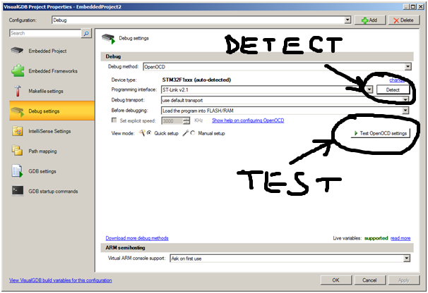
You can now program your board through STLink/v2 interface of your spare board.